Problem: Memory Steer After Ball Joint Installation
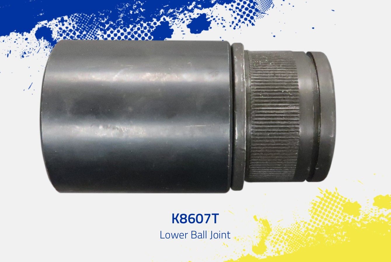
After installing MOOG® K80026 and K8607T ball joints on applications like Ford F-250, F-350, F-450 and F-550 Super Duty trucks and Ram 2500 and 3500 heavy duty trucks, customers may experience poor steering wheel return (also referred to as memory steer), a tight feel on center on the highway and difficulty when turning the knuckle.
This can happen on vehicles with a straight axle 4x4 as a result of ball joint binding due to improper installation. A straight axle design has manufacturing variations horizontally between upper and lower taper holes in the knuckle/axle, and variation between mounting locations of the upper and lower ball joint.
| Vehicles Affected | ||
|---|---|---|
| Years | Make/Model | |
| 1994-1999 | Dodge Ram 2500 (4WD) | |
| 1994-1999 |
Dodge Ram 2500 (4WD & RWD) | |
| 1980-1996 | Ford Bronco | |
| 2000-2005 | Ford Excursion | |
| 1980-1996 | Ford F-150 (4WD) | |
| 1980-1999 | Ford F-250 (4WD) | |
| 1997 | Ford F-250 HD (4WD) | |
| 1999-2022 | Ford F-250 Super Duty (4WD) | |
| 1980-1997 | Ford F-350 (4WD) | |
| 1980-1997 | Ford F-350 Super Duty | |
| 1999-2019* | Ford F-450 Super Duty (4WD) | |
| 1999-2004 | Ford F-550 Super Duty (4WD) | |
*2011-2019 4-Door Crew Cab
Solution: Proper Installation
MOOG ball joints have precision metal tolerances – similar to a crankshaft bearing – and when installed properly, they’ll provide superior service life. Using improper procedures can affect product operation and shorten service life due to the excessive load that these variations can place on ball joints.
Properly installing MOOG Problem Solver K80026 front upper and K8607T front lower ball joints ensure fewer comebacks and more satisfied customers. When completing the repair, pay close attention to the steering gear box, steering damper and front axle universal joints (inspect and properly adjust if needed). These components, if faulty, can cause symptoms similar to failed joints resulting in comebacks and time-consuming diagnostics. For example, binding from internal rust in a steering damper can cause stiff steering and poor steering wheel return to center and/or tight and stiff turning.
Removal Procedure
Before beginning the repair, refer to the factory service manual for proper safety and repair procedures.
Step 1 – Remove the wheel hub, bearing and axle.
Step 2 – With the axle out, inspect the u-joint. If the u-joint is damaged, it should be replaced. Failed u-joints can cause noise and binding.
Step 3 – Remove the tie rod cotter pin and the tie rod end nut. (Figure 1)
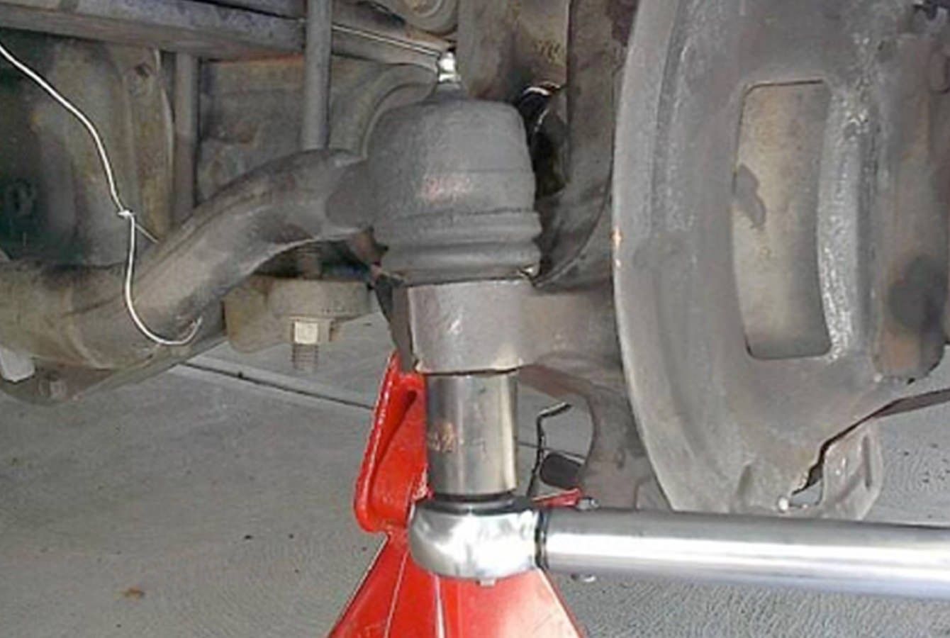
Figure 1
Step 4 – Using the appropriate tool, disconnect the tie rod end from the wheel knuckle. (Figure 2)
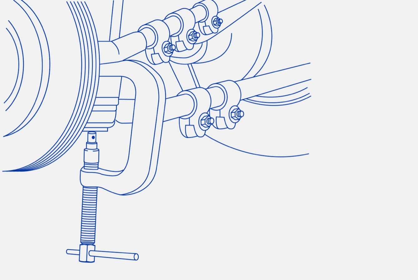
Figure 2
Step 5 – Remove the upper ball joint cotter pin and nut. Loosen, but don’t remove, the lower ball joint nut. Strike the lower and upper end of the axle to loosen the ball joints. (Figure 3)
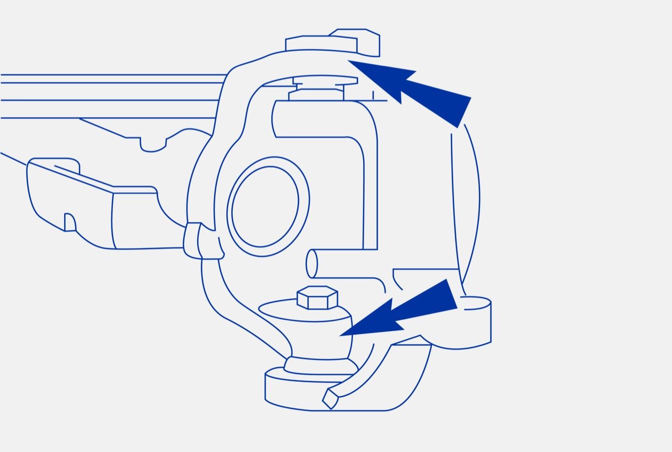
Figure 3
Step 6 – On Ford applications, use the Ford service tool to remove the camber adjuster bushing (also called camber/caster plug). Note it’s position. (Figure 4) It is imperative that you remove the bushing and clean the mating surfaces before proceeding. If it’s not moving freely, you’ll need to replace it.
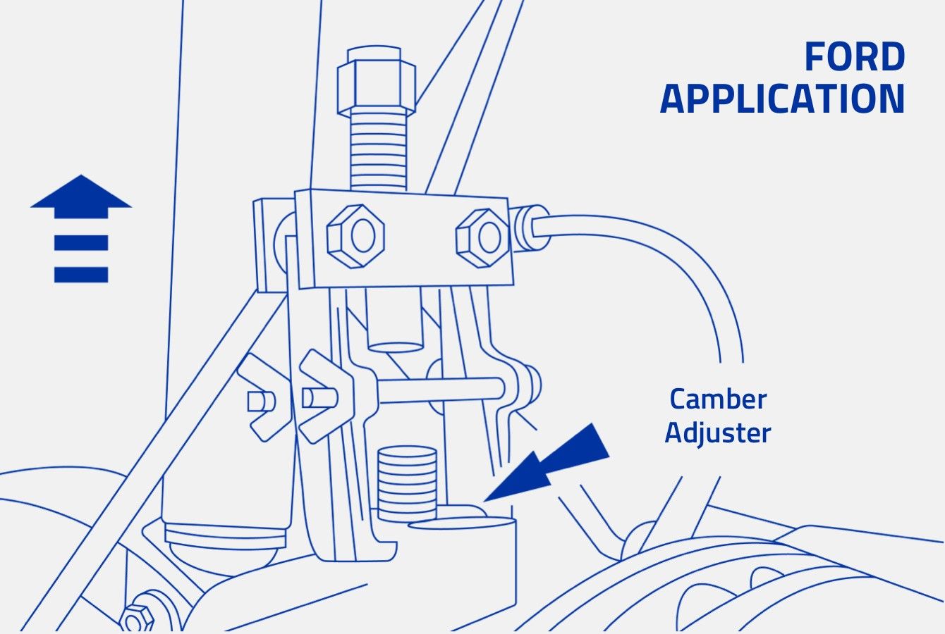
Figure 4
Step 7 – Remove the lower ball joint nut and the wheel knuckle.
Step 8 – Remove the ball joints from the knuckle. It is easier to remove the lower ball joint first. Remove the snap ring, then use a ball joint press and appropriate receiving cups and adapters.
Step 9 – Remove the upper ball joint from the knuckle, utilizing a ball joint press and appropriate receiving cups and adapters. (Figure 5)
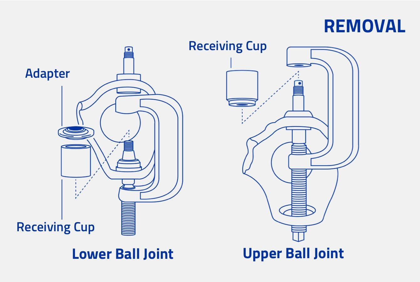
Figure 5
Installation Procedure
Important Notes:
- Thoroughly clean the surface where the new ball joints will seat. Dirty mating surfaces will affect ball joint alignment and torquing.
- Press in the new ball joints by applying force on the stud end. Place the installation cup on the outer step of the ball joint housing. Always press in these ball joints using the outer step and be sure to use the correct size adapter (example shown below).
Step 1 – Install upper ball joint (the upper ball joint must be installed before the lower ball joint).
- A. Clean the knuckle ball joint mating surfaces thoroughly.
- B. Apply a suitable lubricant to the ball joint mating surface and assemble the ball joint into the knuckle.
- C. Assemble the ball joint press components as shown in Figure 6. Check the alignment of all components. Tighten the forcing screw until the ball joint is firmly seated.
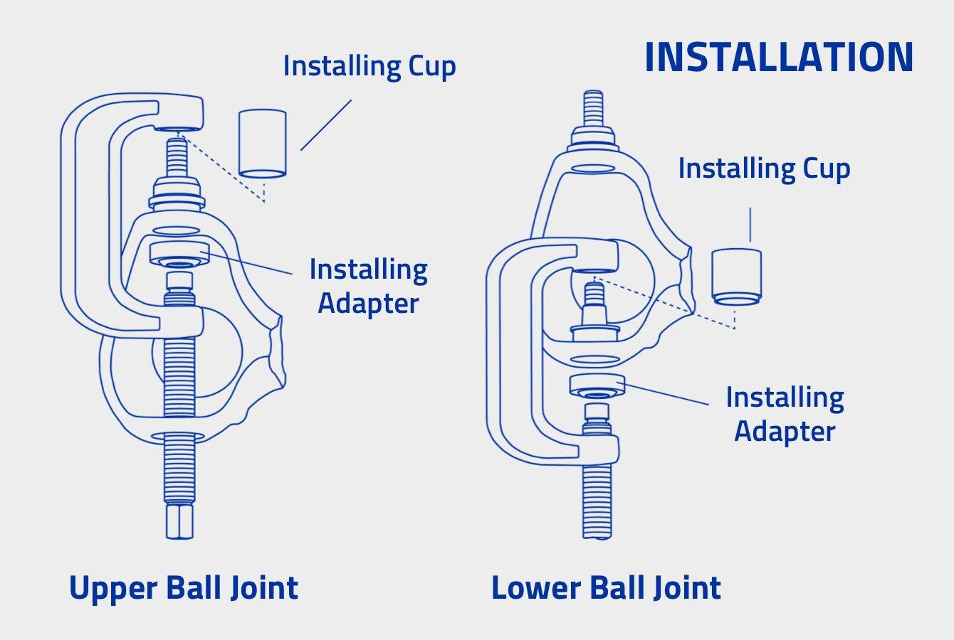
Figure 6
Step 2 – Install lower ball joint using steps A-C of the upper ball joint procedure. Install the snap ring on K8607T.
Step 3 – Install the knuckle assembly to the vehicle according to the vehicle service manual procedures.
Step 4 – Clean the receiving hole and install the camber adjuster sleeve (if equipped).
Step 5 – Position the wheel knuckle onto the axle and install the nut onto the upper ball joint. Don’t tighten the nut at this time.
Step 6 –Apply thread lock and sealer to the threads of the lower ball joint per the OE service manual and install the nut onto the lower ball joint. Don’t tighten the nut at this time.
Torque procedure notes:
- The following torque specifications are for Dana 60 applications as an example. It is important to follow the torque procedures outlined in OE service manual.
- Also, it is important not to use an impact wrench when torquing the nuts. An impact wrench can spin the stud at high speed and cause premature failure.
Step 7 – Tighten the LOWER ball joint nut to 59 Nm (44 ft. lbs.) (Figure 7).
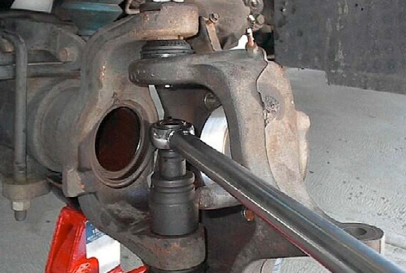
Figure 7
Step 8 – Tighten the UPPER ball joint nut to 94 Nm (69 ft. lbs.) (Figure 8). If necessary, tighten the nut until the cotter pin can be installed. Install the cotter pin. Note: don’t loosen the nut to install the cotter pin. Always tighten to install the cotter pin
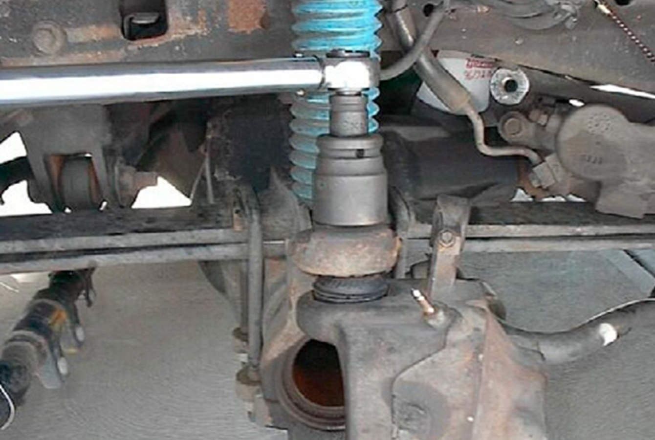
Figure 8
Step 9 – Tighten the LOWER ball joint nut to 204 Nm (150 ft. lbs.).
Step 10 – Connect the tie rod end to the wheel knuckle and install the nut.
Step 11 – Tighten to 115 Nm (85 ft. lbs.). Install cotter pin (same notes as above).
Step 12 – Complete the repair per the OE service manual. Also, a wheel alignment should be performed anytime ball joints are replaced.
Learn more about premium steering and suspension parts, find your car part, or find where to buy your auto part today.
The content in this article is for informational purposes only. You should consult with a certified technician or mechanic if you have questions relating to any of the topics covered herein. Tenneco will not be liable for any loss or damage caused by your reliance on any content.